If you’d prefer to watch the full video, please click below!
Have you ever wanted to turn your old infrared-controlled devices — like your TV, stereo, or air conditioner — into something smart?
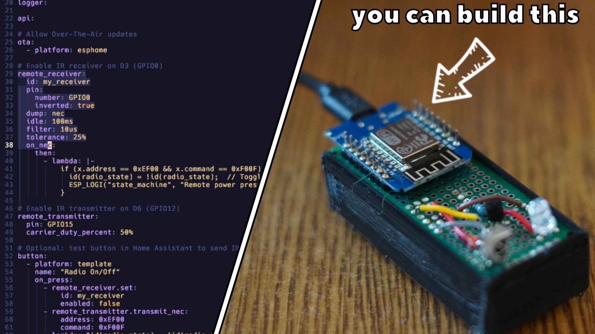
In this tutorial, I’ll show you exactly how to build an ESP8266-based infrared controller that can both receive signals from your existing remote and transmit them back to control your devices.
By the end, you’ll have a fully functional smart IR hub that integrates seamlessly with Home Assistant or Alexa, and stays perfectly in sync with your original remote.
What You’ll Need
Let’s start with the hardware components and why each one matters.
Core Components
ESP8266 D1 Mini – The brain of the project. Small, cheap, and easily programmable via ESPHome.
Infrared Receiver (VS1838B) – Captures signals from your remote control.
Infrared LED Transmitter – Sends infrared commands to your devices.
NPN Transistor (e.g., 2N2222) – Acts as an amplifier switch to drive the IR LED with enough current.
100 Ω Resistor – Limits current to the IR LED.
1 kΩ Resistor – Used for the transistor’s base input.
5 V Power Supply – Powers both the ESP8266 and the IR LED.
PCB or Breadboard – For assembling the circuit.
You can optionally 3D print a simple enclosure to house everything neatly. (I used a compact case from Thingiverse that fits the D1 Mini and PCB perfectly.)
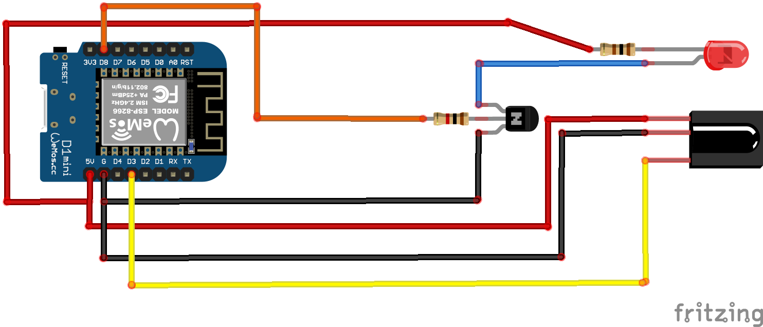
Circuit Wiring
Here’s a breakdown of how everything connects. (You can also refer to the wiring diagram below.)
Infrared Receiver (VS1838B)
Pin
Connection
1 (Left)
5 V (from ESP8266)
2 (Middle)
GND
3 (Right)
D3 (GPIO0)
Infrared Transmitter (IR LED)
Pin
Connection
Anode (long leg)
5 V via 100 Ω resistor
Cathode (short leg)
Collector of NPN transistor
NPN Transistor (e.g., 2N2222)
Pin
Connection
Collector (C)
To IR LED cathode
Base (B)
To 1 kΩ resistor → D8 (GPIO15)
Emitter (E)
GND
This transistor setup is crucial: the ESP8266’s GPIO pins can’t drive the IR LED directly. The transistor works as a switch, using a small control signal from the ESP8266 to handle a larger current from the 5 V line.
ESPHome Configuration
Now that our hardware is ready, let’s set up the ESPHome firmware to handle both receiving and sending IR signals.
Below is a simplified version of the key parts of the YAML configuration:
Each button can send different NEC codes — for example:
Power Toggle
Volume Up / Down
Source Select
Mute
You can add as many as you need by following the same pattern.
Testing It Out
To verify everything works:
Open the ESPHome logs.
Press buttons on your original remote — you should see the NEC address and command codes appear.
In Home Assistant, toggle your new controls.
Use a Flipper Zero, smartphone, or another IR learning tool to confirm that your ESP8266 sends the correct signal.
Once both receiving and transmitting work, congratulations — you’ve built a fully functional infrared smart hub!
Wrapping Up
You now have a complete ESP8266 infrared smart controller that:
Receives commands from your old remotes
Sends IR codes to your devices
Integrates with Home Assistant and Alexa
Keeps your devices’ states in perfect sync
This is an excellent starter project for anyone diving into ESPHome or DIY home automation.
If you enjoyed this guide, be sure to share this article, or subscribe on YouTube for more ESPHome and DIY Smart Projects. Got questions or ideas? Drop them in the comments — I’d love to help out.
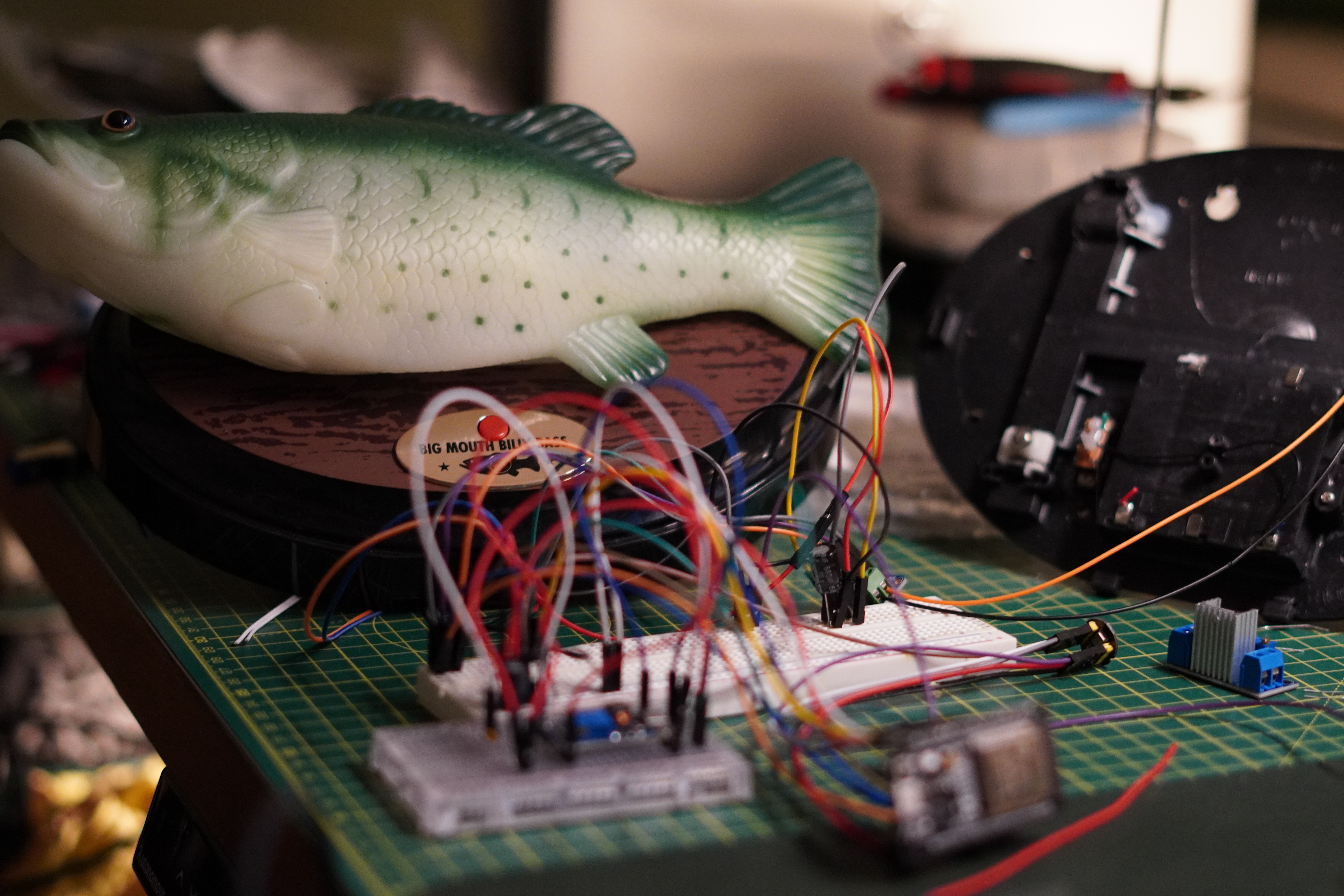
Turning a Singing Fish into a Smart AI Assistant with ESP32 and Home Assistant
Bring your Billy Bass back to life with AI! Learn how to turn a singing fish into a fully interactive smart assistant using ESP32-S3, ESPHome, and Home Assistant’s Summer of AI features. Includes custom wake word, real-time mouth motion, and OpenAI-powered conversations.