
Building a CO2 sensor using a Pi PicoW & automating a home ventilation system part 2
The second in a 3-part series giving a walk-through of creating a custom co2 sensor using the raspberry pi picow and hooking it up to a home ventilation system.

tldr; I built this DIY home CO2 monitor to help me stay alert during my working day, and to ensure clean air ventilation throughout my home. I’m also going to show you how I took this data and built an automated ventialtion system using single room heat recovery units, Apache Flink, Kubernetes, InfluxDb and Grafana. I’ll take you through my whole design and development process from start to finish.
Disclaminer: This is all just for my own fun and learning, I’m absolutely
positive there are far better ways to do quite possibly all of the things
I will go through in these posts. Please bare this in mind when reading ![]()
This is the first in what I hope will become a 3-part series. This first post will take you through how I installed the HR unit and built the CO2 sensor. Links to all sources can be found at the bottom of each post.
Let’s begin.
Nearly two years ago myself and my partner bought and moved into a new home. We both work from home, and quickly noticed after only a few weeks in our new place that most rooms in the house would be stuffy, and we’d both feel sluggish after a couple of hours working in our spaces. As well, in the morning the windows would be saturated with condensation, and from time to time one (or both) of us would wake up with a headache if we didn’t have a small window open.
It wasn’t long after this that i noticed, the previous owner (in his infinte wisdom), decided it was a good idea to block every single vent in the house with insulation board in a vain attempt to improve the heating within the home.
With this newly gained knowledge, I decided it was time to take on my first at home major DIY project.
After much research into various different venting solutions (from new windows to HVAC), I came across single room heat recovery units. I’ll let Wikipedia explain;
Heat recovery ventilation (HRV), also known as mechanical ventilation heat recovery (MVHR), is an energy recovery ventilation system that operates between two air sources at different temperatures. It’s a method that is used to reduce the heating and cooling demands of buildings.
Using these types of fans, I could solve my ventilation problem as well as potentially save on heating costs by introducing them into my home.
After some initial research, I found this. The Blauberg Vento Expert A30/A50. The great advantage of this unit is that it can be controlled over wifi, and this got me excited! Given it’s controlled via Wifi, I could use a CO2 sensor to control the fan speed based off a given CO2 threshold in the room.
So the plan was as follows:
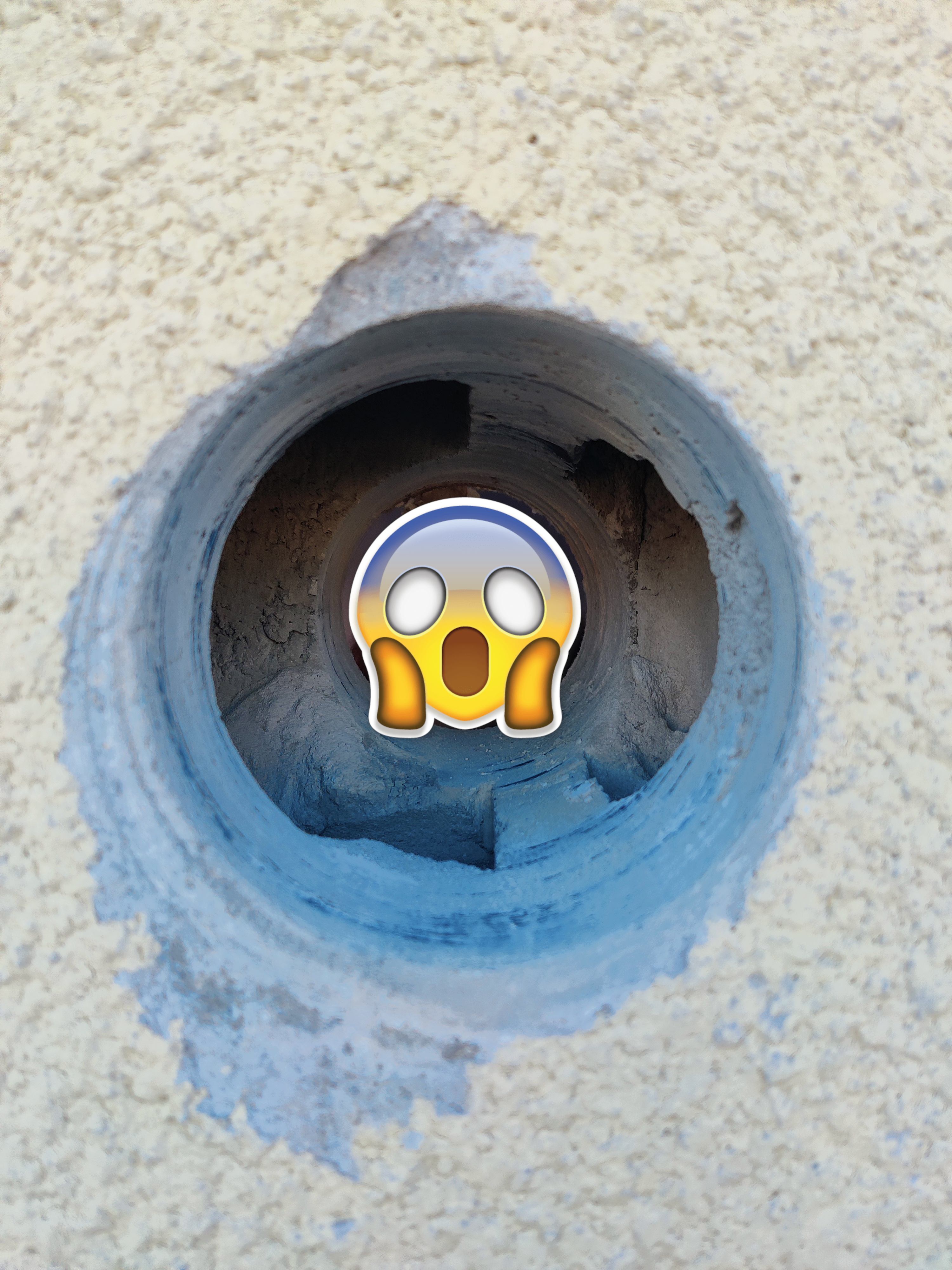
Armed with big bertha (or my somewhat less flamboyant Bosch SDS Rotary Hammer, if we’re being precise) and a 117mm core drill, I embarked on the mission to drill a rather substantial hole in the side of my house. Now, for someone not accustomed to such grand DIY endeavors, let me assure you, it’s a task that requires more than a casual nod to accuracy.

And after what felt like an eternity (about 40 minutes), also mared with the fact I had drilled through a concrete support. I was through.
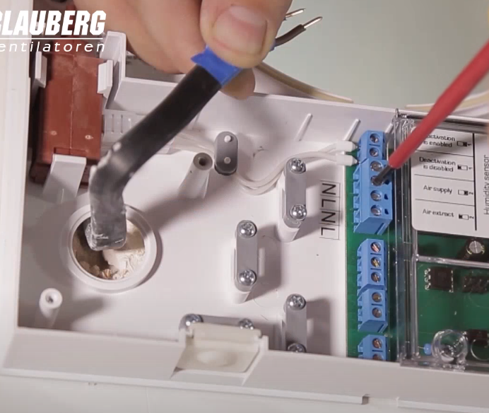
I won’t go into too much detail in regard to the installation, as there are far better videos available on YouTube that can walk you through the process more effectively.
The only, perhaps unique thing I had to do, as I didn’t have a permanent live cable coming from my consumer unit to our main bedroom where the fan was to be installed, was to cut and wire a plug and some 3-core flex cable so the fan could be powered from a socket. Again, this is pretty simple to do. The fan takes a neutral and live connection (no earth), as shown below. Given that the cable I was using was a 3-core flex, I just tied my neutral wire to a Wago connector.
After this, it was just a matter of switching it on, and hoping (praying) I hadn’t messed up the electrics! (I didn’t thankfully).
When I started this project back in mid-2022, you could not buy a raspberry pi anywhere unless you were willing to fork out cash considerably over the odds to grifters in the hopes of securing one. Jeff Geerling did a great blog post on this very subject which is worth a read. I had used the raspberrypi before in other projects and was comforatable with using it’s GPIO layout and I2C interface.
You could however quite easily get a pi pico or picow as those models thankfully were not affected in supply in the same way the pi3 & pi4s were. I also managed to get my hands on a CO2 sensor breakout board for the pi which uses an I2C interface for communication, so I could use this with a pi pico as well.
So, knowing this, I got together the following items to start the build.
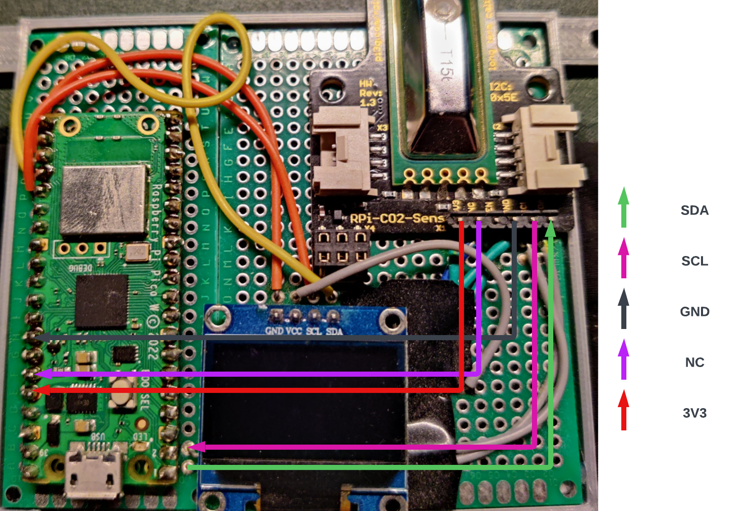
And after waiting a few days for it all to arrive, and then some (very) dodgy soldering, I had this. I’ve marked how I soldered the lines to the pico for some verbosity. To get an understanding of how these pins line upto the GPIO pins on the pico, you can take a look at the Pi PicoW pinout here.
You might notice that I also have the CO2 monitor in a case - this is something I designed and 3D printed myself. You can find the STL files here if you fancy printing it for yourself.

In gearing up for the next stage, I’ve established the Flink Home repository on Github. This project will serve as a comprehensive resource, housing all the code and some detailed instructions to help you navigate the setup process. But first, let’s get acquainted with Micropython.
My initial plan was to utilize the impressive Tinygo project to get everything up and running on the PicoW. However, when I began this endeavor (and even at the time of writing), wireless support for the PicoW is still a work in progress.
So, what’s my vision for the Pico? Well, I aim for it to read and display sensor data on my OLED screen, but I also want it to have the capability to send the sensor data to a broker such as MQTT. This way, I can integrate it into almost anything with relative ease.
import machine
import network
import json
import time
from time import sleep
from machine import Pin, PWM
from ssd1306 import SSD1306_I2C
from umqtt.simple import MQTTClient

# Wakeup
sleep(5)

# Scan for OLED Display
i2c2=machine.I2C(1,sda=Pin(18), scl=Pin(19), freq=400000)
oled = SSD1306_I2C(128, 64, i2c2)

sleep(2)

# Connect to home network
ssid = ""
password = ""

wlan = network.WLAN(network.STA_IF)
wlan.active(True)

# Disable power-saving mode on pico
wlan.config(pm = 0xa11140)
wlan.connect(ssid, password)
sleep(8)

# Wait for connection to be made
max_wait = 10
while max_wait > 0:
    if wlan.status() < 0 or wlan.status() >= 3:
        break
    max_wait = -1
    print('Waiting for a connection...')
    sleep(1)

# Check & Handle connection errors
if wlan.status() != 3:
    oled.text("Connection Failed..", 0, 0)
    oled.show
    raise RuntimeError('Wifi Connection Failed.')
else:
    print('connected')
    oled.text("connected", 0, 0)
    oled.show()
    status = wlan.ifconfig()

# Create MQTT Client
def connectToBroker():
    client = MQTTClient(client_id=b"YOUR_CLIENT_ID",
                        server=b"",
                        port=0,
                        user=b"",
                        password=b"",
                        keepalive=0,
                        ssl=True,
                        ssl_params={'server_hostname': ''})

    client.set_last_will('YOUR_MQTT_TOPIC', json.dumps('{"connection": "closed"}').encode('utf-8'),retain=False)
    client.connect(clean_session=True)
    return client

client = connectToBroker()

def publishToTopic(topic, event):
    client.publish(topic, event)

# Scan for CO2 Sensor
i2c=machine.I2C(0,sda=Pin(0), scl=Pin(1), freq=400000)

print('Scanning i2c bus')

devices = i2c.scan()

if len(devices) == 0:
     print("No i2c device !")
     oled.text("No i2c devices", 0, 0)
     oled.show()
else:
     print('i2c devices found:',len(devices))
     for device in devices:
         print("Decimal address: ",device," | Hexa address: ",hex(device))

lastCo2Val = 0
ipStatus = wlan.ifconfig()

if len(devices) > 0:
    sleep(1)

    while True:
        try:
            # Read from co2 sensor at location, and read block size of 8 bytes
            read_data = i2c.readfrom_mem(0x5E, 0x00, 8)
            co2 = read_data[0].to_bytes(1, 'big') + read_data[1].to_bytes(1, 'big')
            temperature = read_data[2].to_bytes(1, 'big') + read_data[3].to_bytes(1, 'big')
            # reserved value - useful to check that the sensor is reading out correctly
            # this should be 0x8000
            resvd = read_data[4].to_bytes(1, 'big') + read_data[5].to_bytes(1, 'big')
            pressure = read_data[6].to_bytes(1, 'big') + read_data[7].to_bytes(1, 'big')


            curCo2Val = "CO2: " + str(int.from_bytes(co2, "big")) + "ppm"
            curTempVal = "TEMP: " + str(int.from_bytes(temperature, "big") / 100) + "C"
            curIp = "IP: " + status[0]

            # Create JSON event
            event = {
                "event": {
                    "co2": int.from_bytes(co2, "big"),
                    "temperature": int.from_bytes(temperature, "big") / 100,
                    "pressure": int.from_bytes(pressure, "big") / 10,
                    "node_id": 1,
                    "timestamp": time.time()
                }
            }

            oled.text(curCo2Val, 0, 0)
            oled.text(curTempVal, 0, 16)
            oled.text(curIp, 0, 32)
            oled.show()

            if lastCo2Val != curCo2Val:
                oled.fill(0)

            publishToTopic("YOUR_MQTT_TOPIC", json.dumps(event).encode('utf-8'))

            sleep(3)
        except Exception as e:
            print("Could not read sensor data: ", e)
            sleep(5)
The provided code accomplishes the following tasks:
Once these steps have been successfully executed, we move to our event loop. Here, we attempt to read data from our CO2 sensor location. To access our data, we need to read from memory a block size of 8 bytes.
# Read from co2 sensor at location, and read block size of 8 bytes
read_data = i2c.readfrom_mem(0x5E, 0x00, 8)
co2 = read_data[0].to_bytes(1, 'big') + read_data[1].to_bytes(1, 'big')
And because read_data contains ints, we need to convert to bytes and merge.
See datasheet.
Following this, we package up our sensor values into a json object and publish our new event to our MQTT broker.
I already had an MQTT broker setup & running thanks to my Home Assistant
installation, and if you have something similar it should be fairly easy to
start sending events to your broker as well. However, in the event you don’t, I
have put together a simple
MQTT manifest
which uses the hivemq-ce image.
In the next section (coming soon!), I will take you through how (and why) I setup Apache Flink, InfluxDB, Grafana, and got all of this running on my at home K8s cluster.
The second in a 3-part series giving a walk-through of creating a custom co2 sensor using the raspberry pi picow and hooking it up to a home ventilation system.
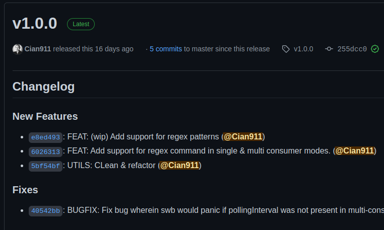
Announcing the release of switchboard v1.0.0 and switchboard-pro.
In this post I introduce you to switchboard. A CLI tool written in Golang to automatically organise files on your machine.